Generator rotor imbalance can come from a number of different sources, i.e. coupling misalignment, component non-concentricity, rubbing, oil issues, bearing, and journal issues. Each has unique characteristics. Thermal sensitivity has its own recognizable characteristics.
If you are unable to operate your Turbine Generator at high field current or VARs because of exceedingly high vibration, your Turbine Generator Rotor just might be thermally sensitive (with apologies to Jeff Foxworthy).

A generator is comprised of several different components, e.g. rotor body forging, copper coils, steel retaining rings, insulating slot cells, turn insulation, and creepage blocks. Each is comprised of unique materials having distinctive coefficients of thermal expansion. The differences in coefficients of the two major components, the rotor body forging and the copper coils, are significant (over 30%) and the associated forces surprisingly enormous. If these forces become restricted or otherwise unequally distributed, the rotor can develop a bend or bow. The development of temperature within a rotor is predominately a by-product of the current or amperage applied to the copper coils. This current or amperage is the source of thermal expansion and any associated thermal sensitivity.
Reversible Thermal Sensitivity:
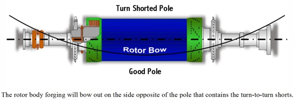
One of the most common causes of unevenly dispersed coefficients of expansion and thermal sensitivity is turn-to-turn shorts within the copper coils of a generator rotor. By their very nature, turn-to-turn shorts reduce the insulation resistance to the flow of electricity. The pole containing the shorts will actually operate at a lower temperature than its counterpart. Lower temperature equates to less thermal expansion and growth in the axial direction. The net result is a rotor body forging that bows out on the side opposite of the pole with the turn-to-turn shorts. The closer that the turn-to-turn shorts are to the pole face (say within the number-1 or number- 2 coils), the more pronounced their effect. Likewise, turn-to-turn shorts in the outer most coils (say the number-5 or number-6 coils) may have absolutely no effect on thermal sensitivity.
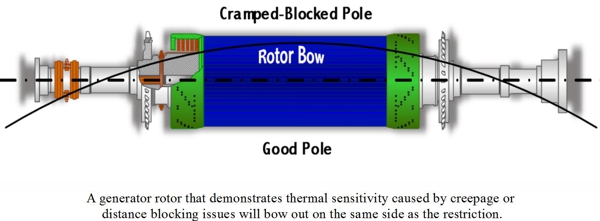
The proper installation of generator rotor end winding creepage and distance blocking is critical to proper and long term operation. Improperly installed blocking and/or blocking that has shifted out of position can cause reversible thermal sensitivity. The main windings of a rotor must be allowed unrestricted axial thermal expansion and contraction. Improperly positioned blocking can cramp or restrict this axial growth, thus causing a bow in the rotor body. A generator rotor that demonstrates thermal sensitivity caused by creepage or distance blocking issues will bow out on the same side as the restriction.

Asymmetrical thermal growth of the generator rotor coils can also be caused by excessive contamination restricting cooling or ventilation pathways. As with turn-to-turn shorts, blocked ventilation can cause uneven axial expansion as some coils operate at higher temperatures than others. The rotor will bow out on the side of the most significant ventilation restriction.
Irreversible Thermal Sensitivity:
There are a number of different conditions that cause irreversible thermal sensitivity. All have to do with restriction of the axial growth of the generator rotor main windings. All are most likely to occur after a complete rewind, partial rewind, major rehabilitation, or repair. With respect to a rotor rewind, it is critical to maintain proper winding (side-to-side) clearances. This entails ensuring that the new ground wall insulation is not too thick. It also means gauging the width of the new or existing copper to assure that it is within proper tolerances. A coil or coils wound too tight will restrict proper symmetrical axial growth and bow the rotor body. A generator rotor demonstrating this type of irreversible thermal sensitivity will bow out on the same side as the most significant restriction.
Radial symmetry must be maintained when performing either a complete or partial rotor rewind. Whether under the rotor body wedges or the retaining rings, inconsistencies in the height or buildup of the windings, coil-to-coil, can restrict the symmetrical axial growth of the rotor windings, bow the rotor body, and generate an imbalance.


If rotor body wedges are replaced, it is of absolute importance that the new wedges have the same cross-sectional dimensions as the originals. Axial restriction can take place if the new wedges are too tight in the wedge groove, or the new wedges have a deeper wedge fit to bottom face dimension.
Some generator rotor designs have only three, two, or even one wedge per slot. Such configurations are much more susceptible to wedge related irreversible thermal sensitivity. Additional safeguards must be employed when these rotor body wedges are removed to facilitate rewind or repairs. It is critical that each and every wedge be trial-fit into its exact position, and fine-tuned as required to assure proper fit.
 Testing for Thermal Sensitivity:
Operational tests can be performed in order to determine whether or not an excessively vibrating generator is thermally sensitive, and whether that thermal sensitivity is reversible or irreversible.
As stated above, a thermally sensitive TGR’s vibration will react to changes in field current. Bear in mind that a Turbine Generator’s vibration may also react to changes in megawatt loading. It is therefore important to ascertain whether excessive vibration is megawatt loading induced or field current induced.
To confirm this one needs to apply a constant field current to the TGR and then increase the megawatt load on the generator by a nominal 50% (+/-10%). Monitor generator vibration, bearing temperatures, voltage, and current. Note any change in Turbine Generator (TG) vibration readings. Maintain this level of megawatt load until all monitored operating characteristics normalize. Next, raise the TGR field current to maximum nameplate rating while maintaining the constant megawatt load.
If the TGR vibration is affected by the increase in megawatt loading, yet not affected by the field current increase, then it is not thermally sensitive. If the TGR is unable to achieve full field current due to excessive increases in vibration or if the vibration or phase angle changes significantly, then the TGR could be defined as thermally sensitive.
As the final part of the on-line test, the field current needs to be reduced to its original starting level. If the TGR vibration returns to its original level as the current is lowered then the thermal sensitivity is considered to be “reversible”. If the TGR must be brought down to turning gear, cooled, and restarted in order to regain acceptable vibration readings, then the thermal sensitivity is considered to be “irreversible”.
Thermal sensitivity can manifest itself at any point in time and for a variety of reasons. It is important that you know how to determine if your specific effects are due to thermal sensitivity, what type of thermal sensitivity you might have, and what developed this phenomena. Your TGM® Generator Specialist has the experience and expertise necessary to help.

Casing Repair – Welding Considerations
/in Turbine Tips /by Mike.LakeWelding is a common method to repair turbine casing cracks, but it must be applied with consideration. Most turbine casing alloys can be welded using either of two distinct procedures: stress relieved and non-stress relieved. The procedure selected is often dictated by time and cost restraints.
Non-stress relieved welds have the advantage of lower cost and shorter outage time. The disadvantage is that the weld can be short lived. The procedure follows this outline: A preheat of about 500 degree F or greater is used. A shielded metal arc weld is performed with a non-matching high nickel content filler. This use of dissimilar metals as filler can lead to low cycle metal fatigue. No post-weld stress relief is performed but the preheat conditions are maintained throughout the process.
The pre-weld residual stress levels in the casing must be carefully assessed to increase the probability of a successful weld. The high levels of residual stresses in the casing can combine with the added stresses of welding to cause uncontrolled distortion and hot cracking during the stress relief phase. Residual stresses generated by the weld passes can be reduced through techniques such as grinding, peening between passes, and peening and grinding. Therefore, the welding procedure must be performed by a skilled contractor.
The best way to control distortion during stress relief is to bolt the casing halves together and place the assembly in the furnace. This would be most applicable to an inner casing that can be easily removed from its outer casing. If only the upper half of the casing is going to be repaired, a thick plate can be bolted onto the horizontal joint as a substitute for the lower case. Distortion can be further controlled by inserting custom fabricated rounding rings or disks into the assembly before thoroughly bolting it together.
If the facility has ample room, a portable furnace can be built on-site. Otherwise, the assembly must be sent out for this process. If the assembly is too large for the furnace, stress relief can be done on a local area of the case, allowing suitable temperature gradients away from the weld areas. Whatever the location, the temperature of the furnace and the assembly must be stringently monitored during the entire stress relief process.
Multiple heat cycles and possible re-tightening of the joint bolting between cycles may be necessary. This is a process which has been refined over the years and continues to get better. Again, it is always a good practice to perform an assessment prior to performing any of the above procedures.
The next Turbine Tip in the series discusses Distortion and Erosion in casing repair.
Casing Repair – Cracking
/in Turbine Tips /by Mike.LakeMost units can be repaired by grinding, welding or by pre-stressed mechanical methods. Finite element calculations show that in many cases, repairs can overcome some of the original design weaknesses and extend useful life by up to 20 years. But before proceeding with a repair, understand the mechanisms of both the casing damage and the proposed repair. Improper repair can be useless or worse.
Cracking is the most common problem on utility units built before 1970. Cracking typically occurs at the steam inlet areas on the HP and IP sections, where transient thermal stresses can exceed the yield point of the casing material. Cracking may be found on the interior surfaces of steam chests, valve bodies, nozzle chambers, seal casings, diaphragm fits and bolt holes.
Every crack must be fully analyzed before attempting repairs and NDE inspection must be performed at a minimum. Radiograph inspections may provide greater assurance by revealing the extent of the crack in relation to its location and the thickness of the surrounding area. Some OEM’s have a detailed customer letter on known areas of potential cracking, their particular process to map out these cracks, and the proposed corrective action and potential life expectancy.
Although grinding is a common repair method, it can increase the potential for new cracks if improperly applied. Cracks in steam chests can potentially expand, making repairs more costly. Grinding on cracks in older machines may reveal voids in the casing, making the condition much worse.
Another problem is that even when an NDE shows that cracks have been removed by grinding, very small undetectable cracks may still be present and may lead to future larger cracks.
Welding of cracks is another common repair method. There are two distinct procedures for welding: stress relieved and non-stress relieved. Non-stress relieved weld repair has the advantage of shorter outage duration but can fail much sooner than a stress relieved weld. This complicated topic will be discussed in our next Turbine Tip in the series.
Mechanical Repairs can be applied to cracks, but must be properly designed to redistribute tensile loading away from the crack area. One method is to apply stitches across the crack. Another method is to place bars or dog bone shapes across previously ground out areas.
A more effective method uses precision machining and the application of a lobe-lock designed through finite element analysis. The material properties of the lobe-lock must be such that it provides maximum pre-load at a certain temperature and a reduced pre-load at that same temperature. The material must also be ductile at all temperatures to prevent cracking of the lobe-lock.
Mechanical repairs have several advantages. The repairs can be performed in place, with no possibility of casing distortion because there is no heating or welding. Machining durations are shorter and easier to quantify. These repairs can also extend life to the area (vs. welding).
A potential disadvantage is that the mechanical repair is conducted on a low cycle fatigue crack and concentrated in an area surrounded by non-cracked material.
The next Turbine Tip in the series discusses stress relieved vs. non-stress relieved welding.
Proper Bearing Loading Helps Reduce Turbine Equipment Failure
/in Combustion Turbine Tips /by Mike.LakeThe main reasons for bearings to wipe are:
Every once in a while a fourth cause appears: High bearing loading.
Proper bearing loading is calculated by the elevations of the bearings, component weights and shaft alignments (bending moments, lateral, torsional). These forces have a direct impact on the stress of the equipment and thus, need to be a part of the equation.
The OEM calculates the elevations and coupling alignments during the design process, based on the catenary curve (or sag chart). Calculations of bearing loadings and alignment are usually accurate based on the design engineers’ mathematical calculations and computer model for the rotor’s geometry, speed, weight, and bearing design.
The following Catenary Curve graphic depicts bearing loading:
Most of the time, high bearing loading is caused by misalignment of the turbine power train from the original design. That is, some force has moved the components from their original alignments. This may include temperature, rotor vibration and other forces associated with the wear-and-tear of the operation.
The source of the bearing failure can be eliminated by carefully measuring and re-aligning to the original specifications. We have also seen examples where the original calculations were not accurate or after years of operation, the bearing pedestals had moved.
Recalculating bearing loading is an arduous and potentially expensive process, so all other contributing factors should be eliminated before attempting this course.
It is important to maintain proper bearing loading to avoid the worst-case-scenario of any impact damage, equipment fatigue, or even catastrophic malfunction. Preventative maintenance can help you be proactive and reduce any bearing challenges that can cause a more severe event in your operation. On three bearing units, it is not uncommon to utilize a dynamometer to check bearing loading during alignment and their adjustments.
PSG can perform the recalculation and re-alignment without the participation of the OEM. If you believe your turbine may be affected by any of the above mentioned reasons for bearing wipe, please contact us today for a free assessment of your current situation.
Power Services Group Announces the Addition of Orbital Energy Services and Turbine Generator Maintenance to its Portfolio of Service Companies
/in News /by Mike.LakePSG presents an alternative to the OEM for plant maintenance services in the power generation and industrial process markets
ANDERSON, SC (PRWEB) March 22, 2017
Power Services Group, Inc. (PSG), headquartered in Anderson, SC, is pleased to announce the joining of the three existing Airco companies, headquartered in Pooler, GA, with Orbital Energy Services (OES), headquartered in Gainesville, GA, and Turbine Generator Maintenance, Inc. (TGM), headquartered in Cape Coral, FL as wholly-owned subsidiaries. These companies have a solid track record and reputation with over 75 years of combined operations.
The parent company for the combined entity will be known as PSG. Together, the companies will provide customers a broad maintenance, repair and overhaul (MRO) solution for all rotating equipment and other critical plant maintenance services. More specifically, PSG’s service offering includes field services, field machining, steam path repairs, valve repair and parts manufacturing, generator inspection and repair, balance of plant maintenance, and specialty code welding. Industries served include power generation (nuclear, fossil, hydro-electric, and wind), industrial, and petrochemical.
“PSG now operates as a turnkey solution provider, setting a new standard of service excellence with an attractive value proposition relative to our competitors. Our safety record, customer focus, proven team, broad service offering, flexibility, and engineered solutions allows us to partner with clients in a manner that has been missing in the marketplace for some time,” said Ronnie Onofry, CEO of Power Services Group.
“Our clients seek a customer-focused, flexible, one-stop-shop for engineering and maintenance services. PSG provides the technical competence required to deliver a more cost-efficient and user-friendly solution. We listen to our customers and work in partnership with them to address the many challenges they face in a very demanding operating environment,” according to Jim Miller, Board Chair of PSG.
PSG is proud to be one of the few remaining U.S.-owned, non-OEM companies in our space. We are confident you will find Power Services Group to be different from other industry players.
MEDIA CONTACT:
Don Dodds
Executive VP Sales and Marketing
Phone: (314) 540-6386
ABOUT POWER SERVICES GROUP
Power Services Group (PSG) is a U.S.-based provider of integrated turnkey solutions in the areas of maintenance, repair and overhaul of steam and gas turbine equipment. PSG also provides balance of plant (BoP) services and equipment to support a wide range of industries, including Power Generation, Oil & Gas, and industrial process. PSG leverages the combined experience and legacy knowledge of its affiliated companies—Airco Inc., Turbine Generator Maintenance, and Orbital Energy Services.
For questions or more information on PSG, please call or visit our website at https://powerservicesgroup.com.
Why Is My Generator Rotor Vibrating?
/in Generator Tips /by Mike.LakeGenerator rotor imbalance can come from a number of different sources, i.e. coupling misalignment, component non-concentricity, rubbing, oil issues, bearing, and journal issues. Each has unique characteristics. Thermal sensitivity has its own recognizable characteristics.
If you are unable to operate your Turbine Generator at high field current or VARs because of exceedingly high vibration, your Turbine Generator Rotor just might be thermally sensitive (with apologies to Jeff Foxworthy).
A generator is comprised of several different components, e.g. rotor body forging, copper coils, steel retaining rings, insulating slot cells, turn insulation, and creepage blocks. Each is comprised of unique materials having distinctive coefficients of thermal expansion. The differences in coefficients of the two major components, the rotor body forging and the copper coils, are significant (over 30%) and the associated forces surprisingly enormous. If these forces become restricted or otherwise unequally distributed, the rotor can develop a bend or bow. The development of temperature within a rotor is predominately a by-product of the current or amperage applied to the copper coils. This current or amperage is the source of thermal expansion and any associated thermal sensitivity.
Reversible Thermal Sensitivity:
One of the most common causes of unevenly dispersed coefficients of expansion and thermal sensitivity is turn-to-turn shorts within the copper coils of a generator rotor. By their very nature, turn-to-turn shorts reduce the insulation resistance to the flow of electricity. The pole containing the shorts will actually operate at a lower temperature than its counterpart. Lower temperature equates to less thermal expansion and growth in the axial direction. The net result is a rotor body forging that bows out on the side opposite of the pole with the turn-to-turn shorts. The closer that the turn-to-turn shorts are to the pole face (say within the number-1 or number- 2 coils), the more pronounced their effect. Likewise, turn-to-turn shorts in the outer most coils (say the number-5 or number-6 coils) may have absolutely no effect on thermal sensitivity.
The proper installation of generator rotor end winding creepage and distance blocking is critical to proper and long term operation. Improperly installed blocking and/or blocking that has shifted out of position can cause reversible thermal sensitivity. The main windings of a rotor must be allowed unrestricted axial thermal expansion and contraction. Improperly positioned blocking can cramp or restrict this axial growth, thus causing a bow in the rotor body. A generator rotor that demonstrates thermal sensitivity caused by creepage or distance blocking issues will bow out on the same side as the restriction.
Asymmetrical thermal growth of the generator rotor coils can also be caused by excessive contamination restricting cooling or ventilation pathways. As with turn-to-turn shorts, blocked ventilation can cause uneven axial expansion as some coils operate at higher temperatures than others. The rotor will bow out on the side of the most significant ventilation restriction.
Irreversible Thermal Sensitivity:
There are a number of different conditions that cause irreversible thermal sensitivity. All have to do with restriction of the axial growth of the generator rotor main windings. All are most likely to occur after a complete rewind, partial rewind, major rehabilitation, or repair. With respect to a rotor rewind, it is critical to maintain proper winding (side-to-side) clearances. This entails ensuring that the new ground wall insulation is not too thick. It also means gauging the width of the new or existing copper to assure that it is within proper tolerances. A coil or coils wound too tight will restrict proper symmetrical axial growth and bow the rotor body. A generator rotor demonstrating this type of irreversible thermal sensitivity will bow out on the same side as the most significant restriction.
Radial symmetry must be maintained when performing either a complete or partial rotor rewind. Whether under the rotor body wedges or the retaining rings, inconsistencies in the height or buildup of the windings, coil-to-coil, can restrict the symmetrical axial growth of the rotor windings, bow the rotor body, and generate an imbalance.
If rotor body wedges are replaced, it is of absolute importance that the new wedges have the same cross-sectional dimensions as the originals. Axial restriction can take place if the new wedges are too tight in the wedge groove, or the new wedges have a deeper wedge fit to bottom face dimension.
Some generator rotor designs have only three, two, or even one wedge per slot. Such configurations are much more susceptible to wedge related irreversible thermal sensitivity. Additional safeguards must be employed when these rotor body wedges are removed to facilitate rewind or repairs. It is critical that each and every wedge be trial-fit into its exact position, and fine-tuned as required to assure proper fit.
Operational tests can be performed in order to determine whether or not an excessively vibrating generator is thermally sensitive, and whether that thermal sensitivity is reversible or irreversible.
As stated above, a thermally sensitive TGR’s vibration will react to changes in field current. Bear in mind that a Turbine Generator’s vibration may also react to changes in megawatt loading. It is therefore important to ascertain whether excessive vibration is megawatt loading induced or field current induced.
To confirm this one needs to apply a constant field current to the TGR and then increase the megawatt load on the generator by a nominal 50% (+/-10%). Monitor generator vibration, bearing temperatures, voltage, and current. Note any change in Turbine Generator (TG) vibration readings. Maintain this level of megawatt load until all monitored operating characteristics normalize. Next, raise the TGR field current to maximum nameplate rating while maintaining the constant megawatt load.
If the TGR vibration is affected by the increase in megawatt loading, yet not affected by the field current increase, then it is not thermally sensitive. If the TGR is unable to achieve full field current due to excessive increases in vibration or if the vibration or phase angle changes significantly, then the TGR could be defined as thermally sensitive.
As the final part of the on-line test, the field current needs to be reduced to its original starting level. If the TGR vibration returns to its original level as the current is lowered then the thermal sensitivity is considered to be “reversible”. If the TGR must be brought down to turning gear, cooled, and restarted in order to regain acceptable vibration readings, then the thermal sensitivity is considered to be “irreversible”.
Thermal sensitivity can manifest itself at any point in time and for a variety of reasons. It is important that you know how to determine if your specific effects are due to thermal sensitivity, what type of thermal sensitivity you might have, and what developed this phenomena. Your TGM® Generator Specialist has the experience and expertise necessary to help.
D11 Issues – Cracks in the HP/IP Shell
/in Steam Turbine Tips /by Mike.LakeOperators can mitigate this potential through a more rigorous NDE of the gland and fit any time the component is exposed, and monitoring HP/IP efficiency and/or pressure for a significant but gradual drop. This reduction may signal imminent failure and advise a shutdown of operations for a major inspection. GE indicates that the “cycle time for repairing cracked packing glands is approximately 25 days, which can become the critical path during a major outage”. This cycle time can significantly extend the OEM’s recommended 60 day plan for a major outage. GE also recommends having a spare N2 packing gland on hand if this additional cycle time will significantly disrupt operations.
TGM® recommends addressing this potential problem with a thorough and ongoing program of performance monitoring in conjunction with robust advanced planning for outages. Our Running Condition Assessment (RCA) program can help identify and evaluate this and other potential operational issues and form the cornerstone of the shutdown planning. A robust, flexible and contingent advanced plan can reduce major outage cycles from 60 days to 45 or even 30 days, depending on the amount of repair involved.
These results can only be achieved with a high level of coordination (well in advance of the outage) between the operator, the outage team, and an array of subcontractors that may (or may not) be called upon if various planned contingencies are realized. A case in point is the N2 packing gland and shell fit. Significant pre-outage planning is required to prioritize the disassembly and NDE of these components in case long-lead time issues are identified. Dust blast and NDE of the upper half of the N-2 packing case should begin as soon as it is exposed and removed; the lower half should be prioritized after the rotor is removed. A repair plan should be in place in case cracks are found, and the repair vendors should be identified, costed, and notified prior to the outage. TGM® has developed a 14 day cycle plan for most cracking issues, using pre-approved TGM®vendors. Our one-year warranty also applies to these repairs.
Most users who have experienced cracking problems have reported varied results. Repairing shell cracks involves many technical considerations and must be performed by experienced and knowledgeable personnel. Please refer to our previous 3-part series on weld repair (Part 1, Part 2, Part 3). We agree with others that once the N2 packing gland starts cracking, it will eventually have to be replaced.
TGM® additionally recommends providing on-site machining equipment in case adjustments need to be made to the packing gland or the shell fit, and for other potential modifications and known potential TIL requirements. Provisions should also be made to perform high-strength on-site weld repairs to correct dimensions or to repair shell cracks in these or other locations.
Summary
The high-efficiency GE D11 Steam Turbine is a valued workhorse in many combined cycle plants. However, the efficiency comes at the cost of many known potential problems resulting from the higher temperature and pressures, close tolerances, and overall complexity of the unit. The potential for forced shutdowns and relatively long outage cycle times can be significantly reduced. This reduction requires:
Please Contact Us for more information on this and other D11 issues.
Why Valve Freedom Testing is Critical
/in Steam Turbine Tips /by Mike.LakeFirst a little background: We stroke valves to make sure debris and contamination have not blocked the operational clearance between the shaft and its bushing, preventing freedom of the valve to operate. A binding Main Stop Valve (MSV) in an emergency shutdown or trip could cause an overspeed condition resulting in extremely high vibration and equipment failure – even possible personal injury or death. Main steam valves should have a closing time of at least 2 seconds. Non-Return Valves (NRV) also need to be exercised on a regular basis to prevent water induction. This occurs when cooler steam condenses in the pipes and feeds back into the turbine. Water induction can cause serious damage, often referred to as a turbine rotor short condition.
Boiler chemistry plays an important role in the build up of deposits. This issue was covered in a previous Turbine Tip HERE.
In higher temperature units, there is a potential for binding of valve shafts due to exfoliation (blue blush) build-up from either the superheater tubes or reheater tubes in the boiler. Blue blush is a common problem on units that have a single axial type of design or an HP-IP type of configuration with elevated steam inlet temperatures. The HP-IP design not only affects the main steam inlet valves but the reheater valves as well. These HP-IP designs commonly operate at 1,000 degrees F inlet steam temperature at both the main steam inlet and reheater locations. This build-up of blue blush comes in from the walls of the superheater tubes or reheater tubes in the boiler and fuses onto the stems or shafts (also bushings). This exfoliation closes up the operational clearance between the shaft and its bushing, resulting in potential binding of the shaft and preventing freedom of the valve to close in an emergency shutdown or trip.
which can damage valve parts, nozzle partitions and the blading (buckets) themselves. Elevated temperatures of the steam can also cause valve shafts or stems to distort and bend, resulting in additional binding problems. With temperatures such as 1050 degrees F, creep is apt to take place more rapidly than a 1000 degree F application.
Now we have a handle on the parameters for determining the frequency of valve freedom testing: Higher steam temperatures, current boiler chemistry, closer stem/bushing tolerances, measured stem runout, and the degree of existing blue blush build up all play a role. If production and manpower are not issues, we recommend daily freedom testing. However, if these issues are a concern, you will have to measure the risk of less frequent testing against these parameters.
If you do not feel comfortable making this decision on your own, the TGM® Running Condition Assessment (RCA) can help. The assessment looks at the condition and performance of the unit while it is running, which means there is no loss of generating capacity and the assessment is easy to schedule. We assess your boiler chemistry and blue blush build up, and consider your operating history and previous outage findings, including as-found and as-left stem/bushing clearances from previous inspections. An opinion on the frequency of valve freedom testing is but one result of the RCA. In addition, TGM® can employ an arsenal of cost-effective testing equipment and inspections to glean a wealth of information about the actual operating condition of the turbine, the generator, and all the ancillaries. TGM® analyzes this data and generates an informative report which assesses potential failure modes and weighs their effect on generating capacity and potential outage duration. Remedies and operational changes are ranked from “easy to implement with maximum benefit” to “hard to implement with minimum benefit”. Operators can then make the most informed and economically-sound maintenance decisions possible.
Click the link HERE for more information on the TGM®Running Condition Assessment.
Why is a Clean Generator a Happy Generator?
/in Generator Tips /by Mike.LakeThe two most common and virulent contaminates are water and oil. Each of these two materials act as an adhesive that binds particulates into a buildup across surfaces throughout a generator. This is especially true of air-cooled machines. Also, water is a conductor of electricity. The ramifications of its presence need no explanation.
Oil contamination is undesirable for two additional reasons. First, it is a lubricant. Electrical windings, and in particular stator windings, are held tightly together through a number of frictional forces. Side packing holds the stator windings tightly within the stator slots side-to-side. The wedge system holds the stator windings radially within the same slots. Hundreds of blocks and miles of lacing secure the stator end windings to one another as well as to surge rings and brackets. Oil contamination leaches in between all these components. Its lubricating qualities facilitates looseness and mechanical fretting. Second, oil is a mild solvent. Over time it will break down the organic binders in paints, varnishes, and even modern epoxies. Degradation of these materials reduces the dielectric strength of the ground wall insulation system and accelerates electrical aging. Oil’s solvent and lubrication properties contribute to mechanical aging by impairing the homogeneous and monolithic character of the stator winding. Oil contamination must be eliminated (to the best degree possible) to ensure the long-term serviceability of a generator. More importantly, the source of the leakage must be remediated.
Opinions vary regarding proper cleaning materials and methodologies. However, it should be considered as best practice to define a cleaning protocol based upon: 1) Type of contamination; 2) Degree of contamination; 3) Type of insulation system, and; 4) Condition/disposition of the insulation system. Cleaning may include simple wipe down, solvent spraying, dry ice blasting, dry media blasting (corn cob, walnut shell, etc.), steam cleaning, or some combination. Positives and negatives are associated with each and should be discussed prior to implementation.
Simply stated, a clean generator is a happy generator. A consistently clean generator runs cooler, stays mechanically-robust longer, and is significantly less prone to electrical tracking and flash-over failure. A clean generator demonstrates superior operation and maintenance practices and helps assure quality service life. How clean is your generator?
How 0.002” Can Ruin a Turbine
/in Steam Turbine Tips /by Mike.LakeOn a three bearing machine the contact area of the coupling faces is also referred to as the friction face. This is where the torque of the coupling bolts exerts the necessary clamping pressure to hold the coupling halves together without any movement. The normal criteria are 0.000″ to 0.001″ interference for the rabbet male to female fit. Clearance is not permitted. Once this fit becomes too loose then any kind of abnormal event, like a full load trip or synchronization of the generator out of phase could cause a small shift of position at the coupling due to the shaft torque. Since the alignment specification is one half of a mil per foot of shaft from the center of the coupling, any movement at the coupling halves can translate into a misalignment problem.
There are basically three components that need to be maintained in good condition: First is the interference fit of the male to female rabbet. We have already described the importance of this. Next is the condition of the friction faces of the coupling. The faces should maintain a surface finish of 63. They should be hand cleaned only and should never be stoned. Last but not least is the integrity of the coupling bolts.The coupling bolts can fatigue and yield over time from being loosened and re-torqued repeatedly. One should check for galls and burrs which might be evident under the bolt heads or on the flat surfaces of the nuts. The coupling bolts should be inspected nondestructively for cracks during every major inspection. All three items are simply mechanical devices which can be overlooked or assumed to be acceptable for continued service. In reality they can cause misalignment, abnormal vibration levels and undue stresses on the rotors.
Although four bearing machines do not have this particular problem, any deviation from any specification can potentially cause problems either immediately or down the road.
Why Use Hydrogen to Cool a Generator?
/in Generator Tips /by Mike.LakeHydrogen was first proposed as a cooling media for rotating electrical machinery in 1925. The first hydrogen-cooled machine, a 12.5 MVA synchronous condenser, was placed into service in 1928. Nearly a decade later, in 1937, the first hydrogen-cooled turbo generator was commission by Dayton Power and Light in Dayton, Ohio – a General Electric 31.25 MVA, 3,600 RPM unit. Coincidently, this was the very same year that the German passenger zeppelin, Hindenburg, met with its fiery demise.
So why use hydrogen to cool a generator? Despite its reputation, hydrogen gas has qualities that make it a superior heat transfer media and internal atmosphere for a generator. Hydrogen is much less dense that air. Cooling fans can move up to fourteen (14) times as much hydrogen as air using the same amount of power. Combine this with the fact that hydrogen conducts seven (7) times more heat than air. At the same time, hydrogen has a higher heat transfer coefficient; meaning it is better at picking up heat from a hot surface. Hydrogen also has approximately the same specific heat characteristic as air, since they both can carry about the same amount of heat.
Hydrogen does not support combustion. It only becomes volatile when mixed with air. What makes the mixture so deadly is the breadth of its explosive range – from as little as 4-percent to as much as 74-percent. The potential energy release from a hydrogen-fueled explosion is enormous:
Due to the volatility of hydrogen gas, the power generation industry employs tried and true procedures for its monitoring, handling, and disposition. Fires and explosions do occur, though their frequency is miniscule in comparison to the sheer number of hydrogen-cooled generators in operation and the vast quantities of hydrogen handled on an annual basis. The positives far outnumber the negatives. Hydrogen has been an internal cooling media of choice for the last eighty years and will continue to be so for the foreseeable future.