Running Condition Assessment

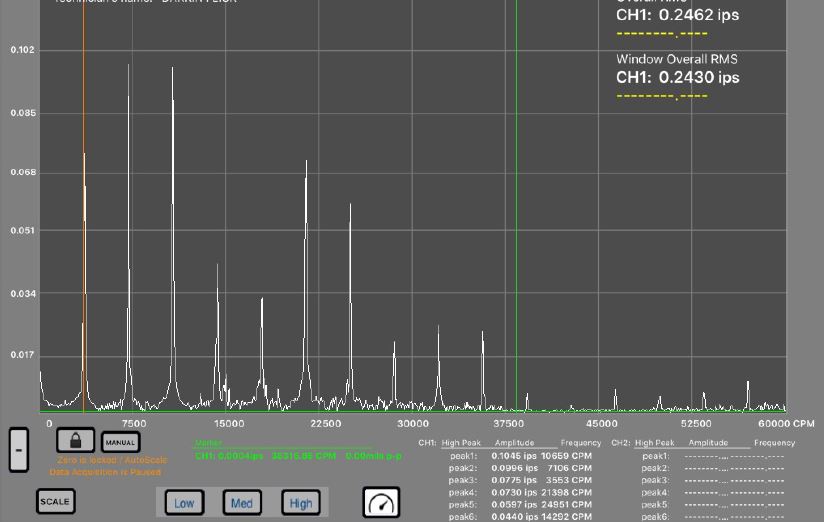
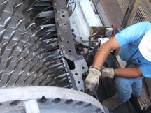
We performed a running condition assessment (RCA) inspection on an industrial GE Steam Turbine, in which we performed a variety of inspection processes to determine the overall running condition of the steam turbine generator and its auxiliary equipment at a facility located on the East Coast, USA. This RCA was completed as an annual inspection to determine the condition of the turbine and generator and to better prepare and schedule the next major inspection for this unit.

We met with the customer and discussed the goals of the Running Condition Assessment, how the unit was operating, and the plan to inspect and evaluate the unit to help determine a time frame for the next major inspection of this unit.

A walk down of the turbine and the visual survey portion of the RCA was completed. The detailed findings were included in a comprehensive 400 page final report. A vibration survey, thermal imaging survey and ultrasonic survey of the unit was performed while on site. The underside of the turbine was surveyed for the condition of the thermal insulation and other visual defects. The auxiliary equipment which included the generator and coolers, lube oil tank, pumps, gland exhaust system, steam traps, and pipe hangers was also surveyed.  Running readings were obtained from local instrumentation as well as from the units control system.

The end result provided the customer with an assessment of how their turbine generator set was currently operating, as well as the trending data from previous years’ assessments.  This data was analyzed and discussed at the customer meeting, allowing the customer to budget and tentatively schedule their next Major Inspection based on the year over year trends and recent assessment findings.  The goal of the RCA program is to help customers extend the duration between Major Inspections, while assessing and correcting minor issues on an annual basis.


ABB Steam Turbine Inspections


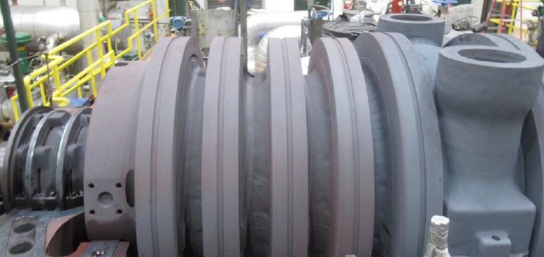
We have performed a number of inspections on ABB Steam Turbines over the years.  We’ve worked on various size ranges, from Industrial to Utility units.  Our Technical Field Advisors are very knowledgeable on the details of the ABB Steam Turbines and the specific procedures to be used for successful disassembly and reassembly of these units.

We attribute our success to our people.  We keep our project teams together as they travel to different job sites around the country.  Our Project Management teams consist of Technical Field Advisors, a Project Coordinator, and Turbine Mechanic Foreman.  The Turbine Mechanic Foreman all have a core group of Turbine Mechanics that travel with them to each job site.   These project teams work together on a regular basis, getting to know one another’s strengths and weaknesses, and look out for each other’s safety.  This continuity of personnel is reflected by our excellent quality and safety record, and is the reason for us being able to deliver successful outages to our customers.

This project team philosophy translates well to inspections of all turbine types, but particularly to the smaller fleets where expertise and continuity can be hard to find.  If you have an inspection coming up on your ABB Steam Turbine please contact us today and learn more about how we will provide you with a successful outage performance.

  Click Here to contact us today.

Shaft Machining

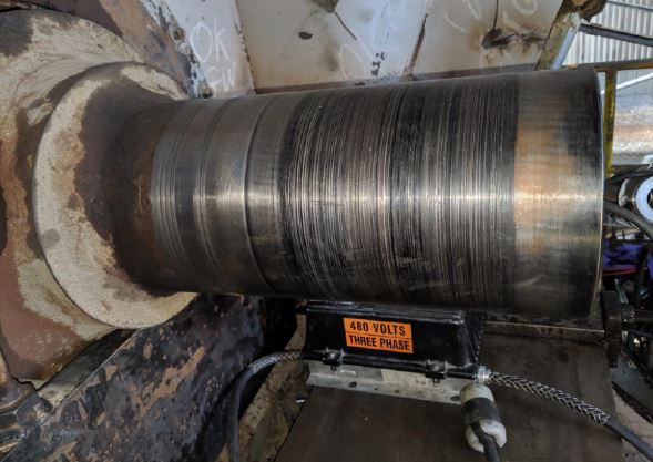
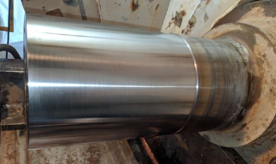
Our Field Machining Division was dispatched to repair an inboard fan shaft for a Utility customer in the Midwest.  We mobilized a total of 4 specialty field machining personnel, and began the process of machining the inboard fan shaft which had severe shaft damage and hard spots.  We cleaned up 100% of the shaft, had hardness checks performed, and then proceeded to final hone and polish.

The total duration of the project was 3 days from start to finish, and the end result was another satisfied customer.  The photos below will give you an idea of the severity of the original shaft damage, as well as the final condition upon completion.  Another great project by our Field Machining Division!


As Found:


Upon Completion:

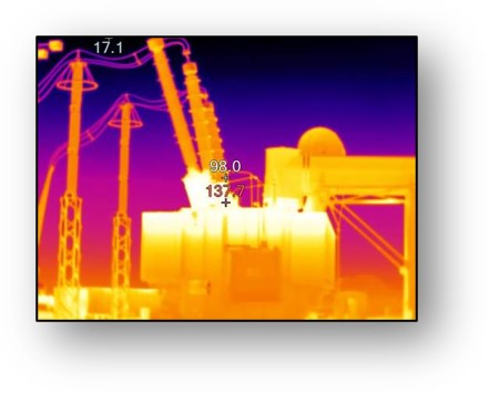
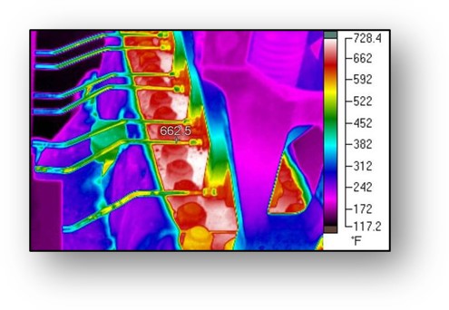
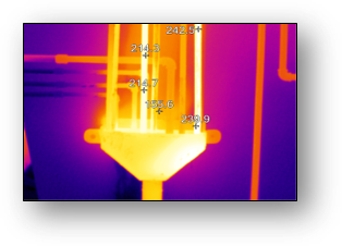
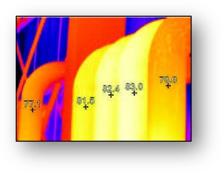
Thermal Imaging of the Power Island

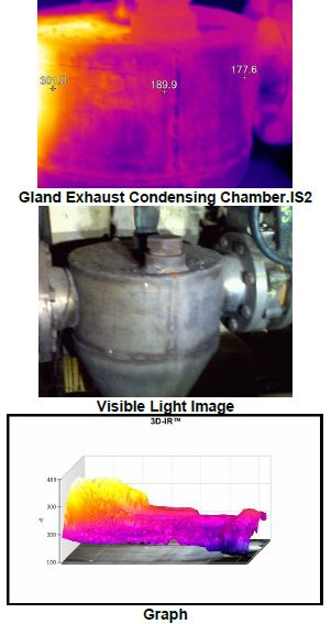
Thermography is a condition-based maintenance technique that is used to monitor the condition of plant machinery, structures, systems, and media (i.e. steam, oil, water, etc.).  By detecting thermal anomalies (i.e. areas that are hotter or colder than they should be), an experienced Thermal Imaging Specialist can locate and define incipient problems within the Power System.  Thermography is just one of the dynamic-state, running-condition assessment tools that can and will detect the presence of issues that may very well disappear during static-state preventive maintenance.  We highly recommend each plant conduct regular thermal imaging assessments of their equipment as part of their standard maintenance practices.


Gas Turbine Compressor Degradation

Contamination and Erosion

All gas turbines experience losses in performance with time and the compressor has a significant impact. In a typical heavy duty axial compressor a 1.0% loss in compressor efficiency will create a 1.1% loss in output.

Compressor fouling is a serious concern and can be mitigated or recovered through proper operational practices. Dirt, oil and debris in the front stages of the compressor can result in a loss of mass airflow, and contamination in the last stages can result in power-robbing drops in the pressure ratio. These foreign objects can also erode or damage surface finishes and airfoil geometry, resulting in reductions in airflow and pressure ratios. Water-washing can partially clean contaminated blades, but recapturing full efficiency can only be achieved by opening the unit and mechanically cleaning the surfaces and replacing damaged components.

While the unit is open, the compressor can be coated to make the airfoils less susceptible to dirt and debris and increase the ability of the water wash to thoroughly clean the airfoils. Adding filtration to the inlet also helps maintain a clean compressor.

Leakage

In a typical heavy duty gas turbine compressor section, air is compressed to many atmospheres pressure by the means of a multiple-stage axial flow compressor. The compressor design requires highly sophisticated aerodynamics so that the work required to compress the air is held to an absolute minimum in order to maximize work generated in the turbine. Any changes to this precise geometry can materially affect performance.

Air leakage through and around components significantly rob performance. One example is a bleed valve which remains open during operation. Another would be a leak at the 4 way joint. While sealing the horizontal and vertical joints are necessary as the machine ages and the casing warps, sometimes all that can be done without purchasing new casings is to manage the leakage. Leaks are more costly to the aerodynamic cycle at stages further down the axial compressor. A leak at an early stage might not be worth the cost of repair.

At the tail end of the compressor rotor is the inner barrel, which provides the inner diameter flow path and the internal support for the exit guide vane (EGV’s). On the internal surface of the inner barrel there is a labyrinth seal called the high-pressure packing seal. On field inspections we often find significant rubbing of the rotor to the labyrinth seals of up to 90 mils. This excess clearance and thus increased airflow results in a loss in performance.

This leakage can be minimized by retrofitting the high-pressure packing seal area with a wire brush seal. The wire brush seal is flexible and will deflect (not wear) if it does contact the rotor. The bristles of the brush deflect in the direction of rotation so that a closer effective clearance can be maintained. The seal even remains intact during transient events where some vibration occurs. Also, there will be less performance degradation over time since the wire brush will bounce back to the original configuration after contact. These losses can only be repaired during an overhaul.

Calibration

Air temperature and pressure can seriously affect performance. Since the gas turbine is an air-breathing engine, its performance is changed by anything that affects the density and/or mass flow of the air intake to the compressor. When measuring performance degradation over time, remember to correct for changes to the reference conditions of 59 F/15 C and 14.7 psia/1.013 bar. Differing ambient air temperatures affect the heat rate. Correction for barometric pressure is more straightforward. A reduction in air density reduces the resulting airflow and output proportionately, but the heat rate and other cycle parameters are not affected.

Humidity is an often overlooked factor affecting performance. Humid air, which is less dense than dry air, also affects output and heat rate. In the past, this effect was thought to be too small to be considered. However, with the increasing size of gas turbines and the utilization of humidity to bias water and steam injection for NOx control, this effect has greater significance.

TGM can help you assess your unit’s existing performance versus its original design and establish a performance measurement process to accurately capture decreases which could indicate the onset of serious problems.

Turbine Generator Maintenance can help you achieve your goals in restoring your machine to its new and clean condition or upgrading its performance to achieve higher output, lower emissions or both.
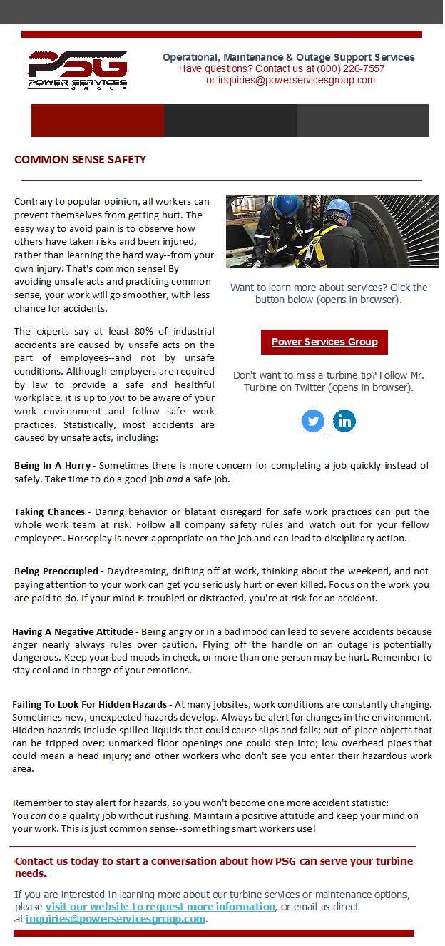
Turbine Tip: Common Sense Safety

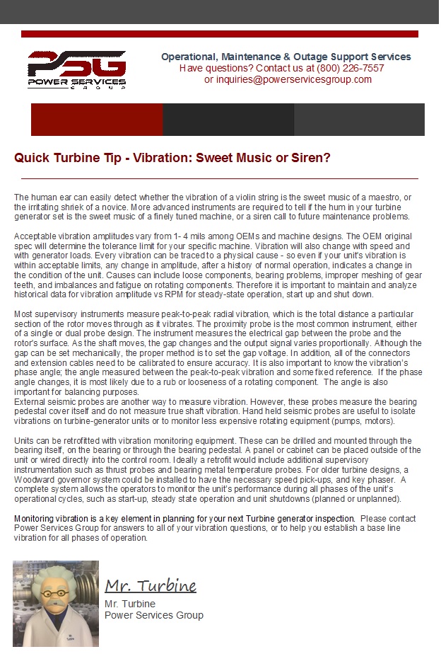
Vibration: Sweet Music or Siren?

Turbine Tip- Tips for Lifting Properly

Casing Repair – Distortion and Erosion

This is Part Three of a three part Turbine Tip series, discussing the most common steam turbine casing problems: cracking, distortion and erosion.

The final Turbine Tip in this series discusses two common steam turbine casing problems – Distortion and Erosion. The repair methods employed – grinding, mechanical repair, welding and stress relief – have their own set of considerations which were covered in previous portions of the series.

Casing Distortion becomes a strong likelihood when the units accumulate operating cycles. The most common causes of distortion are steady state and transient thermal stresses which can occur within all turbine sections (HP, IP, LP). Inner casings distort more easily than outer casings due to their thinner cross-section and higher temperature differentials across the casing walls.

Casing Repair – Distortion and Erosion Turbine Tips6Distortion typically causes problems during disassembly and reassembly. Some examples of this are bolting interferences, gaps at the horizontal joint, galling of the fits and misalignment of the steam path seals. These problems can lead to steam leakage and rubbing. Internal leakage due to distortion reduces efficiency and power output, while leakage to atmosphere and internal rubbing can both cause a forced outage.

Water induction can cause extreme distortion of the inner cylinders. This can damage internal steam path components and lead to forced outages. Inner casings as well as valve bonnet covers can become severely warped and may require extreme measures to remove and replace.

Casing distortion can be corrected by welding, machining, localized heating and rounding discs inserted during stress relief. See previous Tips in the series for considerations in employing these methods.

Damage from erosion affects different designs at different locations, but both rotating and stationary components are vulnerable. Erosion typically takes place in the LP section where steam enthalpy drops below the saturation point. Crossover pipes and inlet areas to the LP section could increase in roughness as the surfaces wear unevenly. Support struts may thin or be cut through.

Moisture erosion can also take place in the exhaust ends of HP and IP sections if the turbine operates for long periods at low load or goes through frequent start-ups. Horizontal joints may erode and leak between stages and stationary blade support rings may erode as well as crack.

Casings, diaphragms, hoods and crossovers are usually made of carbon steel or cast iron. These materials erode approximately 20 times faster than blading material made out of 400 stainless steel.

Erosion can contribute to major damage. Repairs must be aimed at improving the erosion resistance of the steam path and support surfaces. Methods also must be examined for reducing steam moisture content and the size of droplets.

Eroded areas can be rebuilt. Stainless steel or other erosion resistant weld metal can be applied to eroded seal surfaces such as horizontal joints, flow guides and diaphragm inner and outer rings and joints. Fabricated stainless steel liners can be welded inside of crossovers, seal areas and inlet flow areas of casings. They may also be applied over support struts to protect the existing cast iron, steel or low alloy castings.

No stress relief is required in most welding applications. Epoxy or ceramic coatings may be suitable for surfaces that are not suitable for weld overlay.

For more information on your particular application, please contact us at (864) 671-1443 .

This concludes our Turbine Tip series, but we invite you to continue reading our PSG blog for more useful information.

Casing Repair – Welding Considerations

This is Part Two of a three part Turbine Tip series, discussing the most common steam turbine casing problems: cracking, distortion and erosion. 

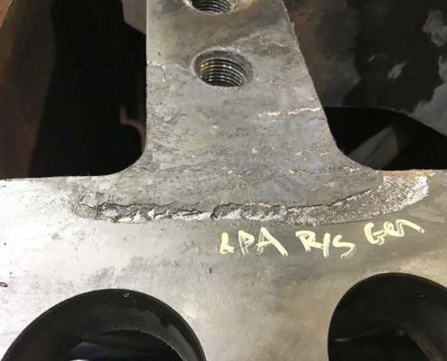
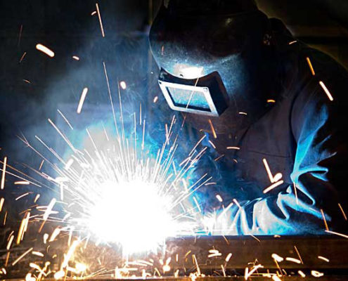
Welding is a common method to repair turbine casing cracks, but it must be applied with consideration. Most turbine casing alloys can be welded using either of two distinct procedures: stress relieved and non-stress relieved. The procedure selected is often dictated by time and cost restraints.

Non-stress relieved welds have the advantage of lower cost and shorter outage time.  The disadvantage is that the weld can be short lived.  The procedure follows this outline: A preheat of about 500 degree F or greater is used. A shielded metal arc weld is performed with a non-matching high nickel content filler.    This use of dissimilar metals as filler can lead to low cycle metal fatigue.  No post-weld stress relief is performed but the preheat conditions are maintained throughout the process.

Casing Repair – Welding Considerations Turbine TipsStress relieved welding offers the best potential for a long repair life, but is complicated and time consuming.  The procedure follows this outline: A lower preheat of about 300 degree F is used. A shielded metal arc or metal inert gas weld is performed with a matching metal content filler. The casing is then placed in a furnace and raised to a temperature of over 1,000 degrees F.  The exact temperature depends on the alloy, the procedure and the application.  Much higher temperatures may be required. There are no problems with differential expansion during turbine operation since the weld uses matching filler metal.

The pre-weld residual stress levels in the casing must be carefully assessed to increase the probability of a successful weld.  The high levels of residual stresses in the casing can combine with the added stresses of welding to cause uncontrolled distortion and hot cracking during the stress relief phase. Residual stresses generated by the weld passes can be reduced through techniques such as grinding, peening between passes, and peening and grinding. Therefore, the welding procedure must be performed by a skilled contractor.

The best way to control distortion during stress relief is to bolt the casing halves together and place the assembly in the furnace.  This would be most applicable to an inner casing that can be easily removed from its outer casing.  If only the upper half of the casing is going to be repaired, a thick plate can be bolted onto the horizontal joint as a substitute for the lower case. Distortion can be further controlled by inserting custom fabricated rounding rings or disks into the assembly before  thoroughly bolting it together.

If the facility has ample room, a portable furnace can be built on-site.  Otherwise, the assembly must be sent out for this process.  If the assembly is too large for the furnace, stress relief can be done on a local area of the case, allowing suitable temperature gradients away from the weld areas. Whatever the location, the temperature of the furnace and the assembly must be stringently monitored during the entire stress relief process.

Multiple heat cycles and possible re-tightening of the joint bolting between cycles may be necessary. This is a process which has been refined over the years and continues to get better.  Again, it is always a good practice to perform an assessment prior to performing any of the above procedures.

The next Turbine Tip in the series discusses Distortion and Erosion in casing repair.