Seconds From Disaster – Overspeed Devices
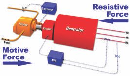
A full loss of generator load can cause the operating speed of a turbine (steam or combustion) to go from normal to catastrophic in a matter of seconds. The electrical load can be lost from generator failure or from external sources such as hurricanes, floods or ice storms downing power lines.

Basically, the generator load is a gigantic magnetic braking force.  In normal turbine operation, the driving force (steam or gas pressure) is equal to the braking force of the generator and the turbine-generator speed is constant. When the braking force is suddenly removed, the turbine force must also be removed before the turbine and the generator components rapidly spin out of control, potentially causing millions of dollars in damage. Your overspeed protection system must be ready to avert this disaster.

Overspeed protection devices can be mechanical (trip weight), electrical or a combination of both.  Units can have a mechanical governor or EHC controls.  Regardless of the mechanism, all overspeed protective devices are designed to stop the steam or fuel from entering the turbine(s) upon an increase in normal speed.  Most overspeed trip mechanisms are set to trip the unit at 110% of rated speed, but most turbine-generators are designed to temporarily operate at up to 120% of rated speed. Lower overspeed settings may be required for certain reheat units and nuclear applications.

Your turbine should have at least two trip devices – electronic and mechanical. Both systems must be inspected and tested regularly – please check your operating manual or call us with any questions.

Failure to remove the driving force (steam or combustion) can unleash torque forces which can destroy your turbine-generator. For example, a modest-sized steam turbine can have a start-up flow of 40,000 lb/hour to synchronize the generator to the grid and close the breaker. As the generator takes on load, steam flow is increased from the initial 40,000 lb/hour to a much greater flow (let’s say 2,000,000 lb/hour) and the turbine goes no faster! That additional 1,960,000 lb/hour steam flow has created torque to drive the generator.

Under a full load rejection, the generator armature reaction that opposes those additional pounds per hour of steam flow is suddenly removed. Now there is an unopposed 1,960,000 lb/hour of steam flow accelerating the turbine. We should not be concerned so much with how fast the turbine will go, because the speed will be way too much. We are more concerned with how fast the turbine-generator will accelerate and how quickly the turbine inlet steam valves will have to close. If the steam is not shut off, the turbine achieves the 120% rating value in seconds. Seconds later, bearings are failing, blades are failing, disks are failing or being pushed into the diaphragms, generator retaining rings are failing, and the rotor is being pushed into the core.

Combustion turbine operators may feel safer because the compressor load acts as an additional brake on acceleration. However, this retarding force will only afford you a few extra seconds. Whether steam or combustion driven, your turbine-generator needs to be ready and personnel need to be ready. There is no warning and you have so little time to act!

Minimize overspeed risk by:

* Having at least two trip devices – electronic and mechanical.

* Properly calibrating your overspeed devices.

* Routine testing to exercise those devices that must operate in an emergency.

* Reporting unusual events that could be indicators of increased risk (a sticking valve that fails to respond to load demand is a good example).

* Not performing tests (exercises) in severe weather conditions where the risk of load rejection is much higher.

Follow the OEM’s recommendation’s for the recommended testing frequency of your over-speed trip and record it’s trip speed.  A good time to test is when you are required to shut down the unit and load is removed from the generator.

The bottom line is that your turbine-generator needs to be ready; personnel need to be ready, as there is no warning and you have so little time to act!

Rotor Axial Position Sensor

It’s an average day in the powerhouse, and suddenly the turbine starts squealing. As you’re running around trying to find the cause, the turbine gives a terrific shudder and shuts down. What you will soon discover is that the thrust bearing reached its limit of wear, sending the blades crashing into the diaphragms.
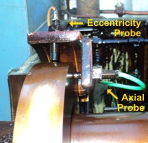
This disaster can averted by monitoring and understanding the Rotor Axial Positioning sensor.  The probes of this sensor are positioned towards the collar so that the axial movement of the shaft in the direction of the generator (the usual direction of rotor thrust) will cause the gap between the probes and collar to increase. If this gap increases, it is an accurate indication that the thrust bearing Babbitt has been compromised and that the rotor is not in its proper axial position. Your I&E Engineer can determine the maximum fail-safe gap based on the minimum measured axial wheel clearance and the total thrust bearing float measurements from the last inspection (if available).

The squeal that you heard just before the machine crashed came from a “squealer ring”, which is sometimes found on older units. Similar to the fins at the end of your car’s brake pad, the ring will emit an unmistakable loud pitch sound when the machine has reached the limit of its axial thrust. If you hear this sound, immediately manually trip the unit and give us a call. Your unit is in immediate need of a major overhaul.

The axial position probes used in this modern supervisory application are proximity probes, very similar to that used in vibration systems. These probes do not contact the collar. The distance (the gap) between the collar and the probe tip is determined by the use of a high frequency magnetic field. As the rotor moves axially, the gap changes and the output signal varies proportionally. The probe tip is adjustable within the bracket assembly for an initial gap setting using a feeler gauge. This mechanical gap setting should be set by the recommended drawing specifications. However, the preferred method is to make final corrections electronically. These probes are usually set to -8.0 volts +/- 1 volt.

Some older machines use thrust trip devices that use oil pressure through a set of nozzles to a collar. These trip devices have been proven to be very reliable. This oil pressure provides a warning should the thrust bearing babbitted pads wear down to a predetermined amount. Further wear will cause the unit to trip due to the high increase in pressure. This trip takes place so that serious damage does not occur to other turbine parts.

RTD vs Thermocouple – Which is Best?

Both RTDs and thermocouples are sensors used to measure heat in scales such as Fahrenheit or Centigrade. Such devices are used in a broad range of applications and settings, each with its own advantages and disadvantages.
Resistance Temperature Detectors (RTDs)
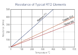
The electrical resistance of metals rises as the metals become hotter, and falls as heat decreases. RTDs are temperature sensors that use the changes in the electrical resistance of metals to measure the changes in the local temperature. For the readings to be interpretable, the metals used in RTDs must have electrical resistances known to people and recorded for convenient reference. As a result, copper, nickel, and platinum are all popular metals used in the construction of RTDs. The easiest way to identify an RTD is by its wire leads. RTDs most often have three wires coming out of them, two of the same color and one of a different color, usually two white wires and one red wire. They can be of other colors but these are the type we most often encounter on a turbine. RTDs can have two wires, however they are not often used in industry any longer as they are not as accurate as three wire sensors.

Thermocouples
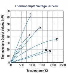
Thermocouples are temperature sensors employing two dissimilar metals to produce a small voltage that can be read to determine the local temperature. Different combinations of metals can be used in building the thermocouples to provide different calibrations with different temperature ranges and sensor characteristics. They are classified as a “type” of thermocouple such as E, J, K, etc. The different types are made from various types of metals and are used for a wide range of temperatures. The type of thermocouple can only be identified by its lead wire color. Thermocouples always have two wires with dissimilar colors.

RTD vs Thermocouple
Because the terms encompass entire ranges of temperature sensors tailored for use under a range of conditions, it is impossible to conclude whether RTDs or thermocouples are the superior option as a whole. Instead, it is more useful to compare the performance of RTDs and thermocouples using specific qualities such as cost and temperature range so that users can choose based on the specific needs of the application.

In general, thermocouples are better than RTDs when it comes to cost, ruggedness, measurement speed, and the range of temperatures that can be measured. Most thermocouples are half the cost of RTDs. Furthermore, thermocouples are designed to be more durable and react faster to changes in temperature. However, the main selling point of thermocouples is their range. Most RTDs are limited to a maximum temperature of 1000 degrees Fahrenheit. In contrast, certain thermocouples can be used to measure up to 2700 degrees Fahrenheit.

RTDs are superior to thermocouples in that their readings are more accurate and more repeatable. Repeatable means that the same temperatures produce the same readings over multiple trials. RTDs produce more repeatable readings which are more stable, while their design ensures that RTDs continue producing stable readings longer than thermocouples. Furthermore, RTDs receive more robust signals and it is easier to calibrate RTD readings due to their design.

Conclusion
In brief, RTDs and thermocouples each have their own advantages and disadvantages. Furthermore, each make of RTDs and thermocouples possesses its own advantages and disadvantages. In general, thermocouples are cheaper, more durable, and can measure a larger range of temperatures, while RTDs produce better and more reliable measurements.

Correct Gap Critical to Rotation Speed

Maintaining the correct gap between the sensor and the rotor is critical to correctly measuring turbine rotor speed. Setting the gap can be problematic if the correct gap is unknown or if it cannot be accessed with a feeler gauge.

First a little background on why the sensor gap is critical: The sensor, or “pickup”, is mounted perpendicular to the shaft, facing a toothed gear fixed to the rotor. Pickups can be either “active” or “passive” (see below). In either case, the pickup counts the teeth by sensing the difference in height between the tip of the tooth and the valley between the tooth. If the sensor is too close, it can’t reliably distinguish between the tip and the valley. If it is too far away, it can’t reliably register the tip. The correct gap will register a voltage differential which can be counted. The electronic circuits determine shaft rotation speed by dividing the number of teeth on the gear into how fast the voltage changes over a period of time.

Always use the manufacturer’s specification data to determine the correct gap spacing for the pickup. If the specification is not available, an initial setting of 0.025″ (0.64 mm) will work in most cases. Once the unit is running, the controls engineer can determine if the output voltage or signal level is sufficient for the type of control used.

Sometimes the pickup gap cannot be accessed with a feeler gauge. If so, an accurate setting can be obtained with a little math and a technique called “counting the flats”. The two most often found pickup sizes are the 5/8″ – 18 and the 3/4″ – 20 thread sizes. If you do the math, the 18 threads per inch (TPI) device will move 1 inch in the mounting hole if it is rotated 18 times. Looking at it the other way, it will move in the hole 0.055 inches if it is rotated one time. Breaking it down further, it will move 0.009″ if it is rotated one “flat” of the hexagonal shaped body or hex nut. In the case of the larger 3/4″ inch device, it will move 0.050″ per one rotation and 0.008″ per “flat”.

To “count the flats”, line up the tooth of the gear as close as possible to the center of the mounting hole until it looks like the picture above. Once the gear tooth is aligned with the center of the hole, screw the pickup down BY HAND until the face of the pickup gently contacts the tooth. Set the gap by unscrewing the pickup while counting the flats from a fixed reference point (can even be a line made by a Sharpie pen). For a 0.025″ gap unscrew it by 2 ¾ flats. The math would be 0.025″ (gap) / 0.009″ (movement per flat) = 2.77 flats or approximately 2 ¾ flats. For the larger pickup size that would be 0.025″ / 0.008″ = 3.1 flats or just tad over three full flats. Tighten up the locknut and you’re done!

There are many different types of pickups out in use today but the most common types used on steam and gas turbines are the “passive” type (sometimes called inactive pickups) and the “active” type. They look very similar but operate quite differently. Very simply, the typical magnetic or “passive” pickup is simply a coil of fine wire wrapped around a magnetized iron core that self generates a voltage. When the tooth of a gear passes in front of the iron core, a small voltage is generated and when the valley between the teeth passes the iron core, the voltage falls off. The “active” type pickup receives power from an outside source instead of self generating it. There is a small transmitter and receiver inside of the device that sends out a signal from the end of the pickup. When a gear tooth passes this signal, it changes the characteristic of the signal that is reflected back to the receiver. The internal electronics then interpret this and send out a voltage pulse. Although the passive sensor generates a sine wave and the active sensor generates a square wave, both sensors count cycles over time, which represents teeth rotation speed.

Please contact Mr. Turbine® for answers to any issue with Steam or Combustion Turbine Controls, or Generator and Exciter Controls for any motive power system.