Casing Repair – Welding Considerations
This is Part Two of a three part Turbine Tip series, discussing the most common steam turbine casing problems: cracking, distortion and erosion.
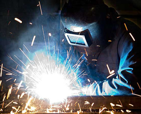
Welding is a common method to repair turbine casing cracks, but it must be applied with consideration. Most turbine casing alloys can be welded using either of two distinct procedures: stress relieved and non-stress relieved. The procedure selected is often dictated by time and cost restraints.
Non-stress relieved welds have the advantage of lower cost and shorter outage time. The disadvantage is that the weld can be short lived. The procedure follows this outline: A preheat of about 500 degree F or greater is used. A shielded metal arc weld is performed with a non-matching high nickel content filler. This use of dissimilar metals as filler can lead to low cycle metal fatigue. No post-weld stress relief is performed but the preheat conditions are maintained throughout the process.
 Stress relieved welding offers the best potential for a long repair life, but is complicated and time consuming. The procedure follows this outline: A lower preheat of about 300 degree F is used. A shielded metal arc or metal inert gas weld is performed with a matching metal content filler. The casing is then placed in a furnace and raised to a temperature of over 1,000 degrees F. The exact temperature depends on the alloy, the procedure and the application. Much higher temperatures may be required. There are no problems with differential expansion during turbine operation since the weld uses matching filler metal.
The pre-weld residual stress levels in the casing must be carefully assessed to increase the probability of a successful weld. The high levels of residual stresses in the casing can combine with the added stresses of welding to cause uncontrolled distortion and hot cracking during the stress relief phase. Residual stresses generated by the weld passes can be reduced through techniques such as grinding, peening between passes, and peening and grinding. Therefore, the welding procedure must be performed by a skilled contractor.
The best way to control distortion during stress relief is to bolt the casing halves together and place the assembly in the furnace. This would be most applicable to an inner casing that can be easily removed from its outer casing. If only the upper half of the casing is going to be repaired, a thick plate can be bolted onto the horizontal joint as a substitute for the lower case. Distortion can be further controlled by inserting custom fabricated rounding rings or disks into the assembly before thoroughly bolting it together.
If the facility has ample room, a portable furnace can be built on-site. Otherwise, the assembly must be sent out for this process. If the assembly is too large for the furnace, stress relief can be done on a local area of the case, allowing suitable temperature gradients away from the weld areas. Whatever the location, the temperature of the furnace and the assembly must be stringently monitored during the entire stress relief process.
Multiple heat cycles and possible re-tightening of the joint bolting between cycles may be necessary. This is a process which has been refined over the years and continues to get better. Again, it is always a good practice to perform an assessment prior to performing any of the above procedures.
