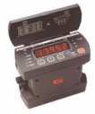
Copper Resistance Testing
 General. The typical generator stator winding consists of three independent circuits or phases. These circuits must be as symmetrical as possible with one another to achieve maximum generator efficiency. This symmetry includes the cross section of each conductor as well as the length or distance from main lead to neutral lead. The Copper Resistance (or Winding Resistance) test measures this “distance” for proper length and high resistant anomalies (i.e. cracks, shorted turns, open circuits, etc.). An increase in resistance from one test to another could indicate the potential for a future winding failure.
Test Setup & Execution. The main and neutral lead connections should be broken and open. The lead ends should be free and clean of surface contamination so that the test probes make good contact. Copper resistance testing is performed with a Digital Low Resistance Ohm Meter (DLRO) test set. The DLRO instrument is extremely sensitive. Poor contact and circuit set-up can either produce erroneous readings or no readings at all.
One probe of the DLRO is connected to one lead of an individual phase, and the other probe connected to the other lead of the same phase. A reading (generally to the fourth decimal place) in ohms resistance is measured and recorded. This same process is repeated on the second and third phase. The ambient air temperature and humidity should be recorded as well.
Interpretation of Results. Temperature significantly influences the resistance of a dielectric as well as a conductor. For this reason, the copper resistance measurement should be corrected to standard (typically 40°C).
The original equipment manufacturer normally records and documents the as-built phase-by-phase copper resistance measurements. These are used as the baseline by which all future readings can be compared.
An increase in in copper resistance indicates the presence of some form of high resistance issue (i.e. broken conductors, cold braze joints, turn-to-turn shorting, incorrect connection, incorrect number of turns or stranding, open circuit). Additional testing will be required to determine the specific cause of the variant reading.
Standard. IEEE Standard 11 8TM-1 978, IEEE Standard Test Code for Resistance Measurement.
Test Equipment. A Megger, Model DLRO-10 or comparable is recommended. Kelvin and Wheatstone bridges are also used to measure resistance.
